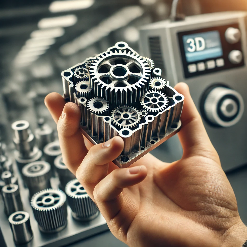
Choosing the correct 3D printing method involves considering numerous factors, such as the intended function, dimensions, and material of the part. At i-make3D, we specialize in guiding you through this selection process to determine the most suitable 3D printing technology for your project.
Our 3D Printing Services Include
1. Fused Deposition Modeling (FDM)
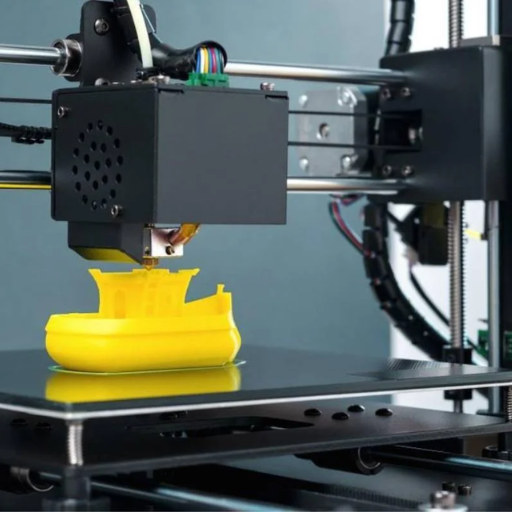
Fused Deposition Modeling (FDM), also referred to as Fused Filament Fabrication (FFF), stands as the predominant additive manufacturing method utilized in desktop 3D printers. This process entails the extrusion of molten plastic from a computer-controlled nozzle, meticulously constructing a part layer by layer.
Advantages:
Most cost-effective 3D printing process for plastic components
Diverse material options available
Widely accessible technology
Disadvantages:
Relatively lower resolution compared to other methods
Visible layer lines may be present
Typical accuracy:
± 0.5% (desktop)
± 0.15% (industrial)
Typical layer height:
Ranges from 50 to 400 microns
FDM Materials:
- PLA (Polylactic Acid): Widely favored for its affordability, rigidity, and color variety.
- ABS (Acrylonitrile Butadiene Styrene): Recognized for its high-temperature resistance and durability.
- PETG (Polyethylene terephthalate): Boasting high impact resistance and favorable thermal properties, also deemed food-safe.
- Nylon: Known for its toughness, flexibility, and resistance to wear and chemicals.
- TPE/TPU: These thermoplastic filaments yield highly flexible parts owing to their plastic-rubber blend.
- PC (Polycarbonate): Renowned for producing exceptionally robust parts resistant to both heat and impact.
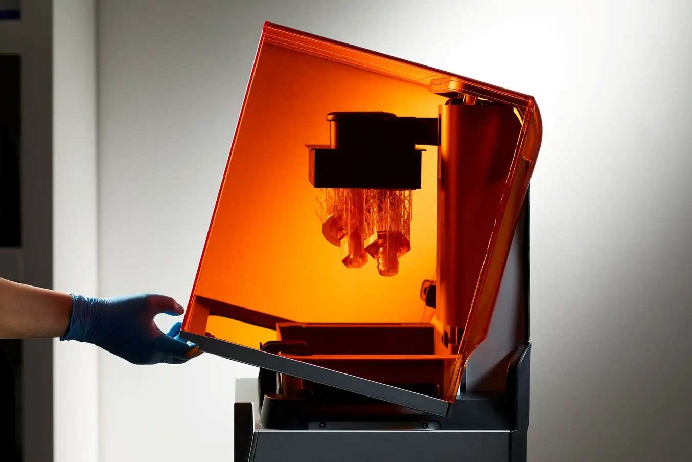
2. Stereolithography (SLA)
Advantages:
High-resolution output
Smooth finish devoid of visible layer lines
Availability of clear material options
Disadvantages:
Higher printer costs compared to FDM
Susceptibility of parts to degradation under sunlight exposure
Requirement for extensive post-processing
Typical accuracy:
± 0.5% (desktop)
± 0.15% (industrial)
Typical layer height:
Ranges from 25 to 100 microns
Stereolithography Materials:
- Resin 8119: A commonly used SLA material featuring a temperature resistance of up to 65°C.
- Resin 8118H: Nylon-like resin renowned for its exceptionally high tenacity.
- Resin 8228: ABS-like resin recognized for its impact resistance and tolerance to temperatures up to 70°C.
- Resin 8338: Our most temperature-resistant resin capable of withstanding temperatures up to 120°C.
- Grey Resin - suitable for A-side visual models with limited functionality; Smooth surface, much smoother in fact than almost all other 3D printing materials. Easy to paint
- Mammoth Resin - Suitable for (large) visual models with limited functionality. Smooth surface
- Transparent Resin - Suitable for (large) models needing a good, smooth, quality surface with a transparent look. Ideal for demo models, accurate models, and models with limited functionality
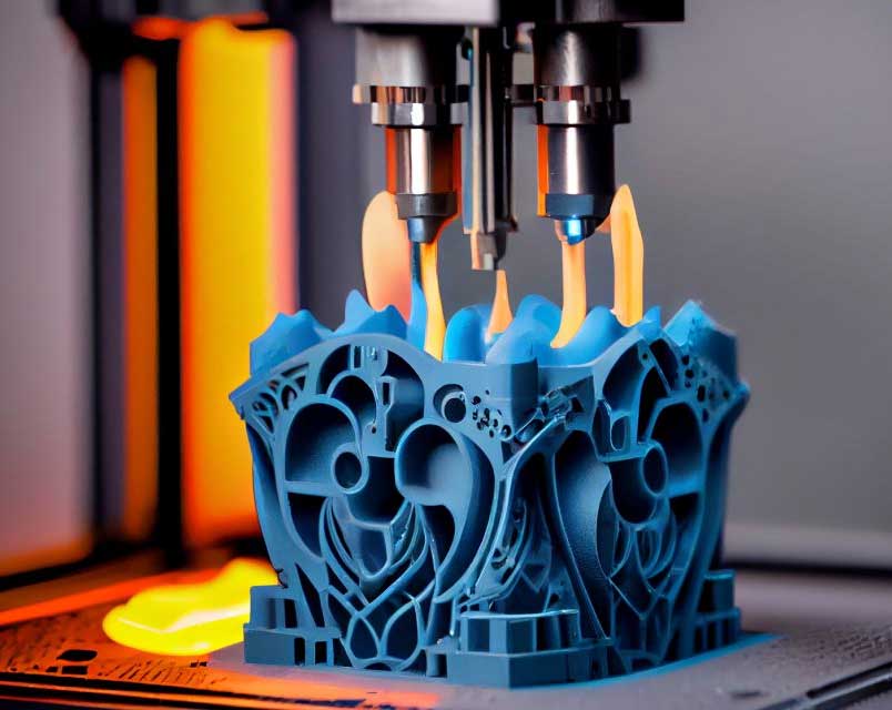
3. Selective laser sintering (SLS)
Advantages:
Consistent mechanical properties across parts
Elimination of support structures
Disadvantages:
Potential for porosity in printed parts
Surface finish may be rough
Typical accuracy:
± 0.3%
Typical layer height:
SLS Materials:
- Nylon PA12: Renowned for its mechanical strength, thermal and chemical resistance, and long-term stability.
- Polyamide: suitable for complex models, prototypes, small series of components, end products, and functional models.
- Alumide: A blend of aluminum-filled nylon offering high stiffness and a distinctive metallic appearance.
- TPU: Highly elastic material boasting exceptional tear and abrasion resistance, along with satisfactory thermal resistance.
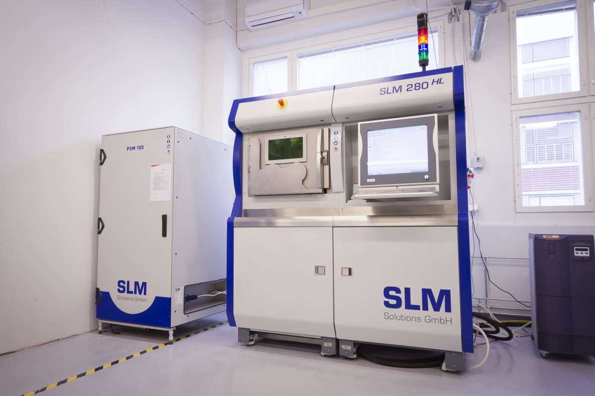
4. Selective laser melting (SLM)
Advantages:
Production of robust and durable parts
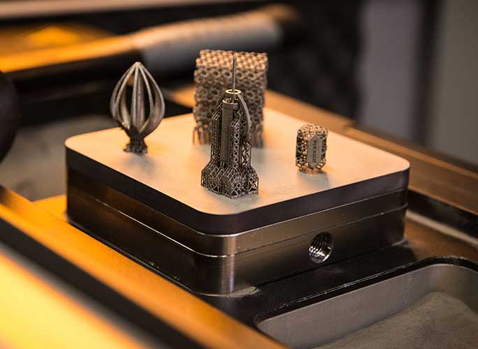
Facilitation of complex shapes
Disadvantages:
Constraints on build size
Elevated costs associated with the process
Typical accuracy:
± 0.1mm
Typical layer height:
Ranges from 20 to 50 microns
SLM Materials:
- Titanium: Renowned for its high-temperature resistance, exceptional strength-to-weight ratio, and corrosion resistance. Capable of superior strength through heat treatment.
- Aluminum: Aluminum alloys offer strength, hardness, and compatibility with intricate shapes or thin-walled parts.
- Stainless Steel: Resistant to wear, corrosion, and abrasion.
- Cobalt: Cobalt-chrome alloys boast high strength, hardness, and resilience to high temperatures.
- Nickel: Nickel alloys exhibit resistance to heat, corrosion, and oxidation, producing parts with strength in high-temperature environments.
- Precious Metals: Ductile metals like gold, silver, and platinum lend a desirable appearance to parts.
DMLS
Advantages:
Vacuum Casting
What is Vacuum Casting?
Vacuum Casting Process:
Step 1: Master building
Masters are 3D solids of your CAD designs. They are usually made by CNC machining or with 3D Printing. After finishing and inspecting the masters, we will move to the silicone mold making.
Step 2: Mold making
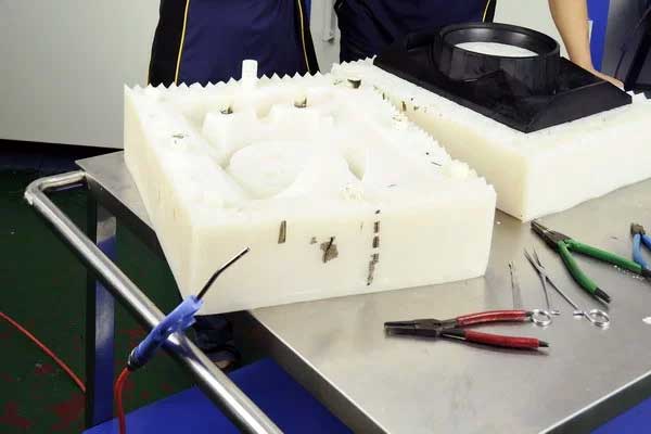
Casting molds are made from liquid silicone. The casting box is half-filled With liquid silicone, heated until the silicone is fully cured and then allowed to cure in an oven for 16 hours. The casting box is filled with extra silicone liquid which is also heated & cured. Once dried, the mold is cut open and the master sample is removed.
Step 3: Make the parts
Casting resins are poured into the empty cavity to create a highly accurate copy of the original. It’s even possible to “overmold” with two or more materials. Silicone molds are typically good for 20 or so copies of the master pattern.
Vacuum Casting Technical Specifications:
- Typical lead time Up to 20 parts in 15 days or less, depending on the part specification and volumes.
- Accurate ± 0.3% (with lower limit on ± 0.3 mm on dimensions smaller than 100 mm)
- Minimum wall thickness To ensure that the mold is filled properly, a wall thickness of at least 0.75 mm is necessary. For best results, we recommend a wall thickness of at least 1.5 mm
- Maximum part dimensions The size of the mold is limited by the dimensions of the vacuum chamber (1900 x 900 x 750 mm) and by the volume of the product (maximum volume: 10 liters)
- Typical quantities Up to 25 copies per mold (depending on the mold’s complexity and the casting materials)
- Color & Finishing Pigment is added to the liquid polyurethane prior to casting, custom painting and texture.
Vacuum Casting FAQ and Answers
Why would I choose vacuum casting over injection molding?
Can I make production-quality parts using vacuum casting?
What happens to the silicone mold(s)? Can I keep them?
The silicone molds used in vacuum casting have a short lifespan, typically around 20 moldings, so we dispose of them after use.
If you wish to keep the 3D printed or CNC machined master model, talk to us directly.
Common Vacuum Casting Applications
- Visual prototypes
- Concept proofs
- Cases and covers
- Low-volume production
- Market testing
- Investor pitches
- Trade shows
